A standalone solar photovoltaic street lighting system is an outdoor lighting unit used for illuminating a street or an open area. Recent advances in LED lighting have brought very promising opportunities for application in street lighting. Combining LED’s low power, high illumination characteristics with current photovoltaic (PV) technology, PV powered street light utilizing LED has become a norm in many places. In today’s application, most of the common High Intensity Discharge (HID) lamps, often High Pressure Sodium (HPS) lamps are being replaced by more low powered Light Emitting Diode (LED) lamps.
A basic solar powered LED street light system components are:
1. Solar Panel or Photovoltaic Module
2. Lighting Fixture – LED lamp set
3. Rechargeable Deep Cycle Battery
4. Solar Charge Controller
5. Light Pole
The Solar Panel will provide electricity to charge the battery during day time. The battery’s charging is controlled by a charge controller. The operation of the LED bulb is controlled by a control circuit either by using sensors such as Light Dependent Resistor (LDR) or voltage or current sensor. All these components will be fixed on a pole as shown in Figure 1 below. The solar panel is mounted at the top of the pole to minimize the possibility of any shading on the panels.
Solar panel A Solar Panel is basically a module that converts light energy (photons) from the sun to generate electricity in direct current (DC) form. There are two types of solar panels, mainly crystalline and thin-film types.
There are two types of crystalline solar panels (see Figure a & b):
- Poly-crystalline Solar Panel
- Mono-crystalline Solar Panel
- Amorphous Silicon (a-Si)
- Cadmium Teluride (Cd-Te)
- Copper Indium Gallium Selenide (CIGS)
- Dye-Sensitized Solar Cell (DSC)
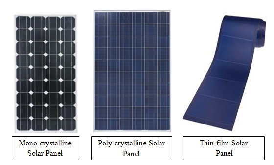
Figure 2: Types of Solar PV Module
Battery
Batteries are used to store the electricity generated by the solar panel. During the day, electricity generated by the solar panels is supplied to the battery and/or the load. When the load demand is higher than the energy received from the solar panels, these batteries will provide stable energy to the load. Solar power applications typically use deep-cycle batteries because they can persist repeated and deep discharges. There are a few types of rechargeable batteries, which are:
(i) Lead-Acid (LA) Battery
These batteries are the most commonly used in solar powered systems due to its maturity in technology and low pricing. They can only be used with low Depth of Discharge (DOD) in order to extend its lifespan. Its DOD ranges from 60%-80%. There are two types of Lead-Acid batteries, i.e. flooded and Valve Regulated Lead Acid (VRLA) batteries which are maintenance free batteries.
(ii) Nickel-Cadmium (Ni-Cad) Battery
Nickel-Cadmium (Ni-Cad) batteries are expensive and disposing of Cadmium is hazardous. Even though they have several advantages over Lead-Acid batteries, such as longer life span, and tolerance for higher discharge, Ni-Cd batteries is not commonly used in solar powered systems due to its high cost and limited availability.
(iii) Lithium-Ion (LI) or Lithium-Polymer (LP) Battery
Lithium based batteries are considered the future of batteries used in solar powered systems. This is due to a number of factors such as high specific energy, high DOD, and higher number of charging cycles. However, due to its higher cost compared to LA type of batteries, they are still not very widely used.
2.3 LED lamp
A LED lamp is a light-emitting diode (LED) product that is assembled into a lamp (or light bulb) for use in lighting fixtures. LED lamps have a lifespan and electrical efficiency that is several times better than incandescent lamps, and significantly better than most fluorescent lamps, with LED able to emit more than 100 lumens per watt.LED are the perfect combinations with solar power as it operates under low voltage, low heat and low power requirement.
Like incandescent lamps and unlike most fluorescent lamps (e.g. tubes and CFL), LED lights come to full brightness without need for a warm-up time; the life of fluorescent lighting is also reduced by frequent switching on and off. Initial cost of LED is usually higher. LED chips need controlled direct current (DC) electrical power; an appropriate power supply is needed. LEDs are adversely affected by high temperature, so LED lamps typically include heat dissipation elements such as heat sinks and cooling fins.
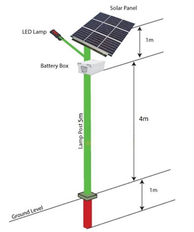
Figure 3: Examples of LED solar street lamps
2.4 Charge controller
Charge controllers are used to control the charging of the batteries. Since the output from solar panels are variable and needs adjustments, charge controllers fetches the variable voltage/current from solar panels, condition it to suit the safety of the batteries. The main functions of charge controllers are to prevent over-charging of batteries from solar panels, over-discharging of batteries to the load and to control the functionalities of the load.
Charge controllers are basically DC-DC converters, where PWM or MPPT technique is used to regulate the switches of the controller. There are three general types of charge controller, mainly:
- Simple ON/OFF Controller
- Pulse Width Modulated (PWM) Controller
- Maximum Power Point Tracking (MPPT) Controller
Most charge controllers operate at three stages to complete the charging cycle of the batteries. These stages vary according to different times and battery voltages. PWM can be employed to control the charging at the stages: \
- BULK stage
- ABSORPTION stage
- FLOAT stage
TECHNICAL SPECIFICATION OF SOLAR STREET LIGHT PROJECT
The following are the specifications for solar PV street light project
Table 1 – Specifications of a 12W Solar Street Light Project |
|||
a |
Specifications of single PV Panel |
Type |
Polycrystalline solar PV panel of 40W each |
No. of Cell |
36 Nos. |
||
Rated Maximum Power (Pmax) |
40W (at 12 noon) |
||
Tolerance |
± 3% |
||
Voltage @ Pmax(Vmp) |
17.18V |
||
Current @ Pmax(Imp) |
2.33A |
||
Short Circuit Current (Isc) |
2.50A |
||
Open Circuit Voltage (Voc) |
21.37V |
||
Nominal Operating Cell Temperature |
47°C ± 2°C |
||
Panel Dimensions (L x W x T) |
(485 x 675 x 35)mm approximately |
||
Weight ( KG) |
4.25 |
||
Standard Test Conditions |
25°C 1.5AM, 1000W/m2 |
||
b |
LED Light |
No. of LEDs |
12 |
Power Consumption |
12W |
||
Maximum Lumens |
1320 |
||
Weight / LED Beam Angle |
1.9KG / 120° |
||
LED Luminous Efficiency |
>= 100 Lm / W |
||
LED working voltage |
6.4V (350ma) |
||
Pole Entry Dia |
Æ37mm |
||
Dimension |
370x135x55mm |
||
c |
Battery |
Battery Type |
Deep Cycle, Sealed Gel, Lead acid |
Capacity |
40 AH |
||
Voltage |
12V |
||
d |
Lamp Pole |
Dimension (L/Dup/D below/T) |
(5000/75/115/3.25)mm |
Pole Distance |
8000mm to 10000mm |
||
e |
Warranty |
5 years limited warranty for the solar PV panels |
|
Note: Above specifications taken from Waaree for PV panel, Photonics for LED lights and Luminous for battery.
TECHNICAL DETAILS
PV MODULE
- Indigenously manufactured PV module should be used.
- The PV module should have crystalline silicon solar cells and must have a certificate of testing conforming to IEC 61215 Edition II / BIS 14286 from an NABL or IECQ accreditedLaboratory.
- The power output of the module(s) under STC should be a minimum of 40 Wp at a load voltage* of 16.4 ± 0.2 V.
- The open circuit voltage* of the PV modules under STC should be at least 21.0 Volts.
- The module efficiency should not be less than 12 %.
- The terminal box on the module should have a provision for opening it for replacing thecable, if required.
- There should be a Name Plate fixed inside the module which will give:
- Name of the Manufacturer or Distinctive Logo.
- Model Number
- Serial Number
- Year of manufacture
- A distinctive serial number starting with NSM will be engraved on the frame of the module or screen printed on the tedlar sheet of the module.
*The load voltage and Voc conditions of the PV modules are not applicable for the systemhaving MPPT based charge controller
BATTERY
- Lead Acid, tubular positive plate flooded electrolyte or Gel / VRLA Type.
- The battery will have a minimum rating of 12V, 40 Ah at C/10 discharge rate.
- 75 % of the rated capacity of the battery should be between fully charged and loadcut off conditions.
- Battery should conform to the latest BIS/ International standard
LIGHT SOURCE
- The light source will be a white LED type.
- The colour temperature of white LED used in the system should be in the range of 5500oK–6500oK.
- W-LEDs should not emit ultraviolet light.
- The light output from the white LED light source should be constant throughout the duty cycle.
- The lamps should be housed in an assembly suitable for outdoor use.
- The temperature of heat sink should not increase more than 20oC above ambient temperature during the dusk to dawn operation.
- The total electronic efficiency should be at least 85%.
- Electronics should operate at 12 V and should have temperature compensation for proper charging of the battery throughout the year.
- No Load current consumption should be less than 20 mA.
- The PV module itself should be used to sense the ambient light level for switching ON and OFF the lamp.
- The PCB containing the electronics should be capable of solder free installation and replacement.
- Necessary lengths of wires/cables, switches suitable for DC use and fuses should be provided.
- Adequate protection is to be incorporated under “No Load†conditions e.g. when the lamp is removed and the system is switched ON.
- The system should have protection against battery overcharge and deep discharge conditions.
- Fuse should be provided to protect against short circuit conditions.
- Protection for reverse flow of current through the PV module(s) should be provided.
- Electronics should have temperature compensation for proper charging of the battery throughout the year.
- Adequate protection should be provided against battery reverse polarity.
- Load reconnect should be provided at 80% of the battery capacity status.
- A corrosion resistant metallic frame structure should be fixed on the pole to hold the SPV module.
- The frame structure should have provision to adjust its angle of inclination to the horizontal, so that it can be installed at the specified tilt angle.
- The pole should be made of Galvanised Iron (GI) pipe.
- The height of the pole should be 4 metres above the ground level, after grouting and final installation.
- The pole should have the provision to hold the luminaire.
- The lamp housing should be water proof and should be painted with a corrosion resistant paint.
- A vented, acid proof and corrosion resistant metallic box with a locking arrangement for outdoor use should be provided for housing the battery.
ELECTRONICS
ELECTRONIC PROTECTIONS
MECHANICAL COMPONENTS